Learn to Generate Electrical Signals Circuit Diagram 1) Using IC 4049. Using only one low-cost CMOS IC 4049 and a handful of separate modules, it is easy to create a robust function generator that will provide a range of three waveforms around and beyond the audio spectrum.. The purpose of the article was to create a basic, cost-effective, open source frequency generator that is easy to construct and used by all hobbyists and lab professionals.
Working Explanation. The operation of this circuit is based on the working principle of a self-triggering oscillator (astable multivibrator), performed by a 555 precision timer circuit (NE555).When the circuit is powered on, The values of resistors (R1, R2) & capacitors (C1, C2) on the left side of the circuit set the pitch of the output tone coming from the audio transducer (loudspeaker
10 Useful Function Generator Circuit Diagrams Explained
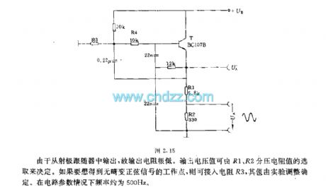
The output level of the sine wave signal is around 500mV RMS. 3) Using Audio Amplifier LM380. The circuit is built around an audio power amplifier device (IC1) utilized in a phase shift oscillator circuit. A three-section phase shift circuit is used to provide feedback between the output and the inverting (−) input of IC1.
A tone generator circuit can be used for various applications such as alarms, bells, indicators, etc. A tone generator consists of a square, triangle, sawtooth periodic wave generator circuits, commonly square wave generators. Such periodic signals produce a beeping sound when connected to audio transducers such as a speaker, piezo, etc.
Simple Audio Frequency Signal Generator Circuit Circuit Diagram
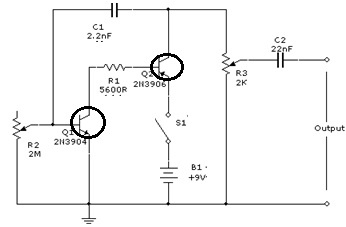
This circuit features a simple thyristor signal generator employing a single thyristor, two resistors, a capacitor and a miniature loudspeaker.. When the circuit is activated by a current source current passes through R1 activating the thyristor.. The thyristor then conducts current charging capacitor C1. As the charging current decreases inversely with the capacitors charging, it gradually Learn how to make a square wave signal generator. With step by step instructions on how to calculate and change the frequency of the square wave. How to Build Audio Filter Circuits. Graham Lambert 3 6 min read. Learn how to build four different audio filters - high-pass, low-pass, band-pass, and notch filters. Detailed instructions and Creating an audio signal generator circuit diagram may seem intimidating and complicated, but with a little bit of knowledge and some practice, anyone can gain the skills necessary to get it done. By following this guide and understanding the basics, it's possible to create your own audio signal generators and reap the many benefits they can offer.