
How To Make RF Transmitter And Reciver At Home Circuit Diagram At the heart of a radio transmitter circuit diagram is an oscillator. The oscillator generates a high-frequency AC signal, which is then modulated with the audio signal to create the radio waves. The oscillator can be a simple tank circuit or a more complex semiconductor-based oscillator like a voltage-controlled oscillator (VCO). 2. Modulator Fig. 4: Pin Diagram and Pin Configuration of HT12E RF Encoder IC. b) RF Transmitter - The RF transmitter consists of an electrical oscillating circuit which generates the radio wave, a modulator which perform hybrid ASK modulation of the wave according to the digital data received from the encoder, and an amplifier which increases the

Building a simple transmitter and receiver is the quickest way to get started on your journey into the world of RF. It is also a lot of fun. This tutorial provides an excellent introduction to building a simple digital communication system. Martyn Davies provides a good overview of modulation, RF circuits and programming with an Arduino. RF Basics, RF for Non-RF Engineers - Texas Instruments
A Diagram of an Rf Transmitter and Receiver Circuit Circuit Diagram
The term RF stands for "radio frequency" and the RF transceiver module will always work in pairs because it needs a transmitter and a receiver to send and receive data. The transmitter can only send information and the receiver can only receive information, so data can always be sent from one end to the other, not the other way around.

Components needed for an RF transmitter circuit. An RF (Radio Frequency) transmitter circuit is used to transmit signals wirelessly in the radio frequency range. It consists of various components that work together to generate and transmit the RF signals. Some of the key components needed for an RF transmitter circuit are discussed below: 1
Simple Design of RF Transmitter and Receiver Circuits Circuit Diagram
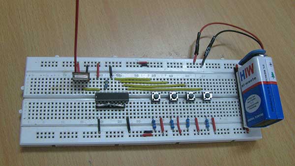
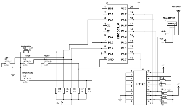
How RF Transmitter and Receiver Circuit Works. The HT12E encoder IC's 4 data pins are connected to the 4 push buttons. The push buttons provide 4-bit data to the HT12E encoder IC. Then the IC converts these 4-bit data into serial data and this serial data will be available at the DOUT pin (pin17) of the IC. This output serial data is given to the RF Transmitter module. The basic block diagram of an RF transmitter and receiver consists of several key components. The transmitter section includes a modulator, an amplifier, and an antenna, while the receiver section comprises an antenna, a tuner, a demodulator, and a decoder. enabling the design and implementation of effective wireless communication systems
